
Setup Guide for Using FSK RTTY on an Icom IC-7300 with N1MM+ Logging and MMTTY software using a Single USB Cable
Objective
The primary objective to use FSK (Frequency Shift Keying) instead of AFSK (Audio Frequency Shift Keying) with N1MM contest logger, with full rig control and a spectrum display, using an Icom IC-7300 transceiver and a single USB cable from the radio to the computer. Generally, with the Icom 7300, you would need a second cable (CI-V) to have both radio control and FSK RTTY. However, it is possible with only a single USB cable by using software called a virtual serial port emulator.
FSK has a few pros and cons. The pros include the availability of the Twin Peak Filter (TPF) on the Icom 7300, which boosts the reception of the mark and space frequencies for better RTTY decoding. FSK also avoids the need to adjust the sound card device level for transmission. However, the required setup for maximum functionality with the IC-7300 is more involved, which is why I documented these instructions.
This guide is specially for the IC-7300 but the steps should be very similar for any Icom (or other brand) transceiver which uses the CI-V protocol. The concept of using the Virtual Serial Port Emulator should also apply to other radios where a single USB port limits the functionality. This guide only covers using RTTY with one radio. It has been tested on Windows 10 and 11 Home Editions only.
Warning: During the process of setting things up the radio might go into transmit mode unexpectedly. It is best to use a dummy load and set the radio power output to the lowest setting available until you are sure the software is operating correctly.
Required Steps
- Configure Icom IC-7300
- Install and configure VSPE (Eterlogic Virtual Serial Port Emulator)
- Install MMTTY – Full version (If not already installed)
- Install N1MM+ (If not already installed)
- Configure N1MMM+
- Configure MMTTY to Run Under N1MM
Step 1: Configure Icom IC-7300
If you have not already done so, download and install the Icom driver software before connecting the radio to the computer. Then, connect the radio via a USB cable and identify the COM port it is using. One way to do this is to open “Device Manager” on the PC, connect the radio, and see which COM port is added.
On the IC-7300 set the mode to RTTY and adjust the audio monitor as you prefer using the Multi-Function knob. Next make the following settings on the IC-7300 (click the menu item arrow to display settings):
Menu > Set > Connectors>
DATA MOD: USB
USB Serial Function: CI-V
Menu > Set > Connectors>CI-V>
CI-V Baud Rate: 19200
CI-V Address: 94h (for single transceiver stations)
CI-V Transceive: Off
CI-V USB -> REMOTE Transcieve Address: 94h
CI-V USB Port: Unlink from [Remote]
CI-V USB Baud Rate: 115200*
CI-V USB Echo Back: ON
Menu > Set > Connectors> USB SEND/Keying>
USB Send: RTS
USB Keying (CW): DTR
USB Keying (RTTY): DTR
Inhibit Timer at USB Connection: ON
Menu> Set> Function>
Time-Out Timer (CI-V): 3 min
RTTY Mark Frequency: 2125
RTTY Shift Width: 170
Note that some of these settings might need to be different, but only if they are consistent with the settings in the programs we are going to use; therefore, it is best to use the above settings with this guide. The CI-V Address should only be changed if additional radios that use the CI-V protocol (mostly Icom) are used simultaneously on the same network
Step 2: . Install and Configure VSPE (Eterlogic Virtual Serial Port Emulator)
The virtual serial port emulator allows us to have both FSK and rig control through software using only one cable to the IC-7300.
Download VSPE from http://www.eterlogic.com/Downloads.html.
(Note: this guide was tested with version 1.5.8.489)
You can use either the 64- or 32-bit versions however the 64-bit version has some minor limitations unless you buy a license. This is primarily a limit of five devices. For this project a licensed version is not required however there is a great deal of support for ham radio applications so I would encourage you to support the company.
Unzip the downloaded file, extract all, and run SetupVSPE.msi as a user with administrative privileges by double clicking or right-click, Install.. This will install a Windows Service named “EterlogicVspeDeviceManagerService.” This service (and the kernel driver) are required and will restart after every reboot. You should never need to, but you can restart it if needed using Task Manager, services page.
Make sure the radio is on and connected via a USB cable, and that it has a COM port assigned for the radio (hint: check device manager). Start VSPE and dismiss the License message or choose “Continue with Limitations”.
Click on Device, Create New Device. For Device Type: Choose Virtual Splitter (optionally enter a title and description). Then click “Next.”
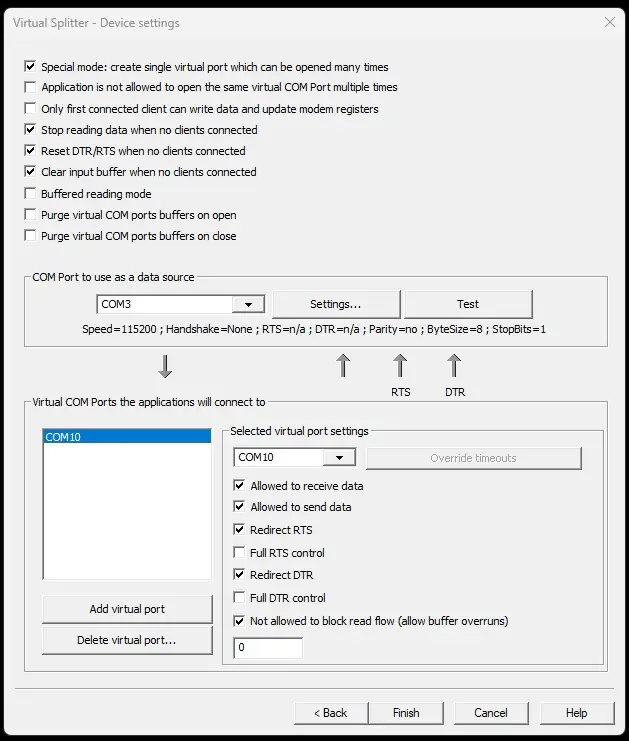
Leave the check box defaults as shown in the upper section, except do check “special mode…”.
For “COM Port to use as data source” choose the COM port assigned to the radio (as shown in Windows Device Manager). In this case it is COM3. Click the “Test” button and verify it works OK. If it does not, click on “Settings” and verify that it matches the radio’s COM port settings which we set up in step one.
In the lower section, use the dropdown to select an unused COM port. Set to any unused Com Port number. For this guide, use COM10. If COM10 is already in use, choose any unused COM port and substitute that number for COM10 in the rest of this guide. Leave defaults as shown except do check the last box, “Not allowed to block read flow (allow buffer overruns).” The settings window is shown below (using COM 3 to COM 10 in this example).
Then click Finish to create the virtual device. To start the virtual COM port splitter, right click on the device in the list and then left-click “start,” or click the green arrow in the toolbar. VSPE should show that the initialization is OK. You can also check device manager to verify you have the new COM port.
You can either leave the VSPE application running, or choose to close it, both while continuing to use the virtual serial port. If you choose to close the application then you will see a warning that the current configuration will be lost after a reboot. In the unlicensed version this is always the case. Click Yes to confirm you want to close the application, then on the next screen be sure to uncheck, “Delete all devices when closing the application” and click OK. You can avoid the second window by going to menu item “Tools, Program Settings” and setting “Ask for confirmation when closing the application” to NO.
If you have the licensed version of VSPE then you can save the settings (using File, Save config file as). Then when you start VSPE you can load the config file. Or you can just double-click your saved config file.
Step 3: . Install MMTTY
Skip to step 4 if you already have the full version of MMTTY installed and operational.
Install the MMTTY full version (not the engine alone) because the full version has a version of EXTFSK that is required for this configuration. The current download link is https://hamsoft.ca/pages/mmtty.php.
After MMTTY is installed, you can close it. There is no need to manually launch MMTTY when using it with N1MM because N1MM will start it when you open a N1MM digital window.
Step 4: . Install N1MM
Skip to step 5 if you already have N1MM+ installed.
To install N1MM, follow the directions at the N1MM website, currently at:
https://n1mmwp.hamdocs.com/getting-started/installing-and-upgrading-n1mm-logger/
For a new install, enter your station data before proceeding.
Step 5: . Configure N1MM
Make sure VSPE is running and the virtual COM port is showing in window’s Device Manager before starting N1MM.
Choose menu option: Config, Configure Ports…, then the Hardware tab (top line). Enter these values:
Port: COM10 (Or use the port that you redirected the radio’s port to using VSPE. Do not use the original radio’s COM port. In this guide, we use COM10).
Radio: IC-7300.
DIGI: Not checked.
CW/Other: Checked.
Under Details, click Set and match the settings in the following screenshot:
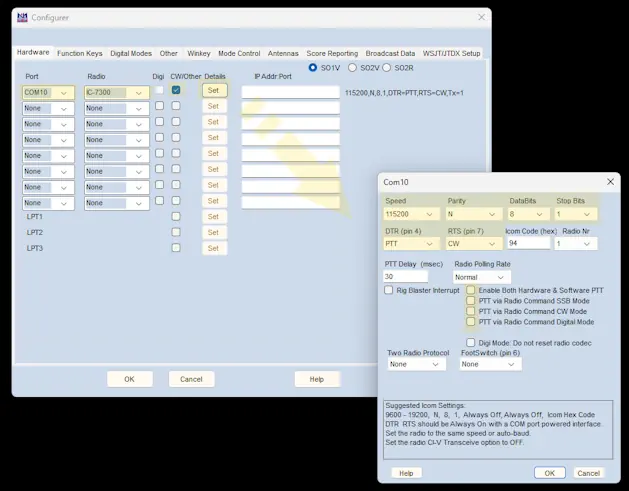
Do not use the suggested Icom Settings shown at the bottom of the window. The “Icom Code (hex)” value is usually the Icom default of 94 h; however, if you have changed it in the radio settings, then change it here also.
Then, click OK on the details window pop-up screen (but not the Configurer window).
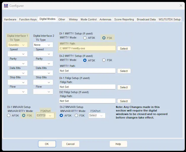
Next, switch to the Digital Modes tab.
Enter the setting shown in the next screenshot. Adjust the path to mmtty.exe as needed for your system. After making these settings, do not click OK.
Next switch to the Mode Control tab and enter these settings:
- Mode recorded in log (left column): Use radio mode (default)
- Mode sent to radio (right column): RTTY: set to RTTY; DIGI: set to USB
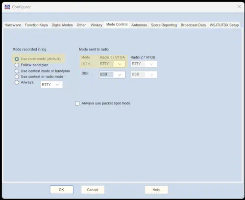
Now click OK. If at this point you get a message that com X port is in use, just close and restart N1MM.
Step 6: Configure MMTTY to Run Under N1MM
From N1MM+, open the Digital Interface Window (Window> Digital Interface). Under the Interface menu window, choose MMTTY. The MMTTY “RTTY Engine 1” window should appear.
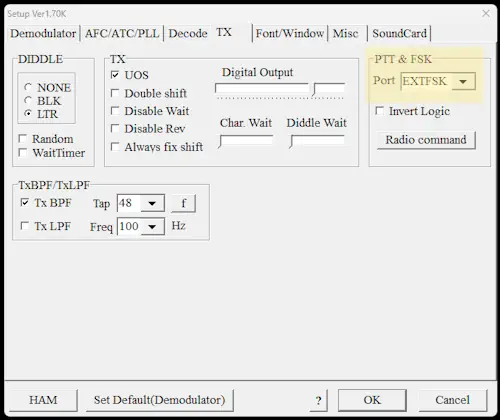
From the “RTTY Engine 1” window (MMTTY), choose Option (O), Setup(O) (or type Alt-O, Alt-O), and then click on the TX tab. In the section on the right side labeled “PTT & FSK”, click the Port down arrow and choose Port: EXTFSK. It is near the bottom of the list. See the next screenshot.
You can ignore the “Radio Command” button because we will use N1MM+ for rig control. Note that if you are using a printer port (LPT) connection with a 64-bit version of Windows OS, then you should choose EXTFSK64. Otherwise, use EXTFSK.
Do not click OK. Go to the Misc tab. For “Tx Port,” select the bottom option: COM-TxD(FSK).
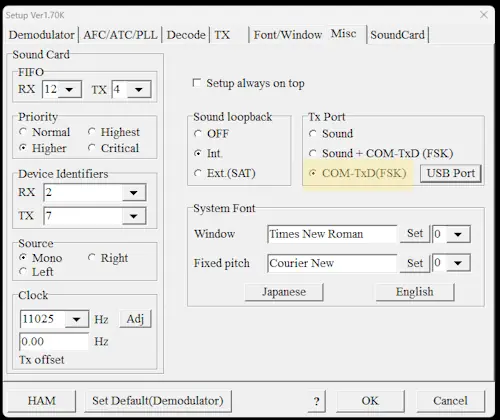
Click the USB Port button and choose option “A: Normal,” then close the USB Port Option window. Do not click OK.
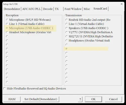
Go to the Soundcard tab and set these values:
- “Reception”: Select the Icom 7300 soundcard. This is typically Microphone (USB Audio CODEC).
- “Transmission”: Select any empty option. We use an empty option because we are using FSK and not a sound card for transmission.
Now click OK. The “EXTFSK” (or “EXTFSK64”) window should also open. It might be hidden (use Alt-Tab to locate it). If the EXTFSK window does not open, then go to N1MM, close the digital Interface (DI) widow, then reopen it using the N1MM Entry window menu choice “Window, Digital Interface.”
Change the settings in the EXTFSK window as shown:
- FSK output: DTR
- PTT output: RTS
- Inv. FSK and Inv. PTT boxes are blank.
- Port: COM10 (or whatever port you created with VSPE). Status should show OK.
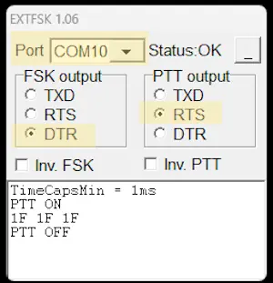
Manually set the radio to RTTY mode and verify that you can transmit RTTY from MMTTY (using red TX and TXOFF buttons) and also from the Digital Window of N1MM+. When you start and stop transmitting you should see PTT ON and PTT OFF in the EXTFSK window as shown in the above screenshot. While transmitting RTTY without sending text, MMTTY is sending the LTRS character for synchronization. This is represented with the Hexadecimal value “1F” in the EXTFSK window.
This concludes the RTTY operation setup. If you have not already done so, configure your selected contest in N1MM, along with your personal settings. Good Luck in your next RTTY Contest!
Restarting the Configuration
Start with N1MM, MMTTY, EXTFSK and VSPE all closed (not running), and the IC-7300 powered off.
Turn on the IC-7300 and set the mode to RTTY on the IC-7300.
Start the VSPE application. If you have rebooted the computer then you need to recreate the virtual splitter device (for unlicensed versions) or reload the device configuration file (for licensed versions where you have saved the configuration). If you have not rebooted the computer then the virtual splitter device should be shown. Once virtual splitter device is shown in the device list, start it if it is not running. Verify that the message “Success: […] Initialization.. OK” is shown in the lower log window.
Start N1MM+.
Open the Digital Interface window. Switch the Interface to MMTTY if needed. The RTTY Engine window should also open.
Check that EXTFSK (or EXTFSK64) shows “Status: OK.” If you don’t see the small EXTFSK window, use “Shift-Tab” to find it.
Make a short transmission to check operation.
Miscellaneous Tips and Bugs
More help in setting up N1MM for a RTTY contest is at: https://www.rttycontesting.com/tutorials/n1mm/plus/config-plus/
However, there are some essential differences between those instructions and the setup used in this document, so be sure to go through this text last, making any needed changes such as COM port speed, PTT control, etc.
Note that the radio must have “M. Scope” activated in order to have the spectrum display from N1MM.
If you have the XY Scope selected (View(V)>XYScope) in the RTTY Engine window, and it does not fill the XY Scope area, then resize the entire RTTY Engine window slightly.
If you see endless “Divide by zero” error boxes appear when you start N1MM+:
- Force close N1MM+ from Windows OS Task Manager.
- Open “Mmmty.ini” in a plain text editor. The default file location is c:/ham/MMTTY/Mmtty.ini
- Change the window size values in the [Window] section. Any change to the values of “WindowWidth” and “WindowHeightRM” should work.
- Then restart N1MM+.
Many unexplained problems are frequently due to stray RF. Use a good quality USB Cable with ferrite beads. To reduce RFI, consider adding ferrites, lowering power, relocating the cable, using a more resonant antenna, etc.
I seem to have an occasional problem where MMTTY loses the following setting:
Option (O)> Setup(O)> TX tab, PTT & FSK, Port: EXTFSK. In those cases, I need to change the port back to EXTFSK to get it working.
Document Version 3.0 (01 MAR 2026). Author: Gordon Lyman, W4ZD, with many thanks to the following for posting helpful information online: N5NHJ (I5NHJ), AA2MF, WT2P (and no doubt many others). Comments welcome at email: W4ZD.73@gmail.com
© 2023, 2024, 2025, 2026 by Gordon Lyman (W4ZD).
Licensed under CC BY-NC-SA 4.0